 How R/C Radios Work
This page explains how hobby-class R/C radios work, what signals ESCs and servos use, what EPA/trim/etc means, and the differences between AM/FM/2.4GHz.
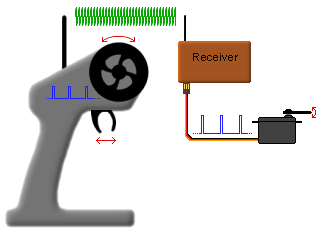
How the radio and receiver work together
|
Any R/C radio, no matter if they are AM, FM, or 2.4GHz, uses a precise pulsewidth signal to control servos and speed controllers (ESCs).
|
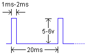
Radio Pulses
|
What are these pulses I am talking about? ESCs and servos require a continuous stream of 1ms (milli-second) to 2ms pulses, which occur every 20ms. Actually, it doesn't have to be exactly 20ms as long as it is fairly close to that and consistent. The voltage level is whatever you are using for a BEC. If using a 5v BEC, the pulses will be close to 5v. If using a 6v BEC, the pulses will be close to 6v. And so on. The picture at right shows what a typical signal would look like at one of the receiver's outputs. |
|
|
This interactive demo shows what the signal pulses look like for the throttle and steering of a typical pistol grip transmitter. Use the mouse to move the slider control to emulate the steering, and move the trigger to emulate the throttle. The output waveforms will change as the inputs are changed. An aircraft/boat/tank transmitter is basically the same, except there can be several more channels and the some controls do not "snap" back to a neutral/center position when the user lets go. |
What do the terms EPA, trim, servo reversing, and exponential rate mean?
Any R/C radio, no matter if they are AM, FM, or 2.4GHz, use a varying pulsewidth scheme to control servos and speed controllers (ESCs).
-
EPA stands for End Point Adjustment. Normally, signal pulses are between 1ms (min) and 2ms (max), but adjusting the EPA can make these less or more than their normal values.
This might be useful if you have a servo that has too much range. You can reduce the EPA so that instead of 1ms to 2ms pulses, it sees 1.1ms to 1.9ms pulses, and the servo's travel will be reduced. Likewise, if the servo doesn't have enough range, you could set the endpoints to 0.9ms and 2.1ms for greater servo travel.
When setting the EPA, be careful not to go too far as servos can be ruined. If they hit some kind of mechanical limit, the servo motor will stall and pull a lot more current which can damage the BEC and/or servo. -
Trim refers to the default center point. Generally, the steering and throttle trims for pistol style radios are set so they output 1.5ms pulses, which is exactly in between 1ms and 2ms. Adjusting this control will adjust the center point to be a little more/less than dead center.
This might be useful for the throttle channel where you may want a tiny bit of braking when you release the throttle. So, you set the trim so that it activates the brakes slightly when you release it. You could also use this to tweak the steering servo if the vehicle still turns slightly right or left when the steering wheel is in the center position. So, you adjust the trim so the tires point exactly straight ahead when you release the steering wheel.
It should be noted that VERY slight changes in the trim should be used. If you need to change the trim quite a bit to get the desired result, you would be better off adjusting the servo linkage and keeping the radio trim at or very near 0 if you can. -
Servo reversing does what the name implies; it reverses the direction of the servo. Instead of the radio outputting 1ms-2ms pulses, it outputs 2ms-1ms pulses.
This would be useful if your tires are turning in the opposite direction of the steering wheel. Also, some radios (particularly Futaba) require you to reverse the throttle channel to work with most ESCs. -
Exponental rate refers to pulse rate of change. Instead of a steady and constant increase/decrease of pulsewidth over the control range, the pulses change at an expontial rate. It's a little difficult to explain, but here's an example:
- Turning the steering knob 25% from center, the vehicle's wheels turn left or right only 12.5%.
- Turning the steering knob 50%, the wheels turn 25%.
- Turning the steering knob 75%, the wheels turn 50%.
- Turning the steering knob 100%, the wheels turn 100%.
This setting may be useful for high speed vehicles to help control steering. At high speed, even a little change in the steering knob can make a big change in vehicle handling. So, adding exponential steering allows finer control to make smaller changes in steering.
The interactive demo below shows what effect that EPA, trim, amd servo reversing have on the pulse stream. Use the mouse to move the steering wheel and note the pulsewidth. Click the links to set the EPA, trim, and servo reversing, then note the pulsewidth again while moving the steering wheel.
|
|
Set EPA to 90% Set EPA to 100% Set EPA to 110% Set trim to -10% Set trim to 0 Set trim to +10% Reverse Servo |
Pulse width:
|
How does a "fail-safe" work?
A fail-safe device monitors the pulse stream and specifically looks for the following conditions:
- Pulses which are too close together. This may indicate another radio is transmitting on the same frequency.
- Irregular pulse frequency. If the pulse frequncey changes from the 20ms figure, it may indicated noise interference or another radio transmitting on the same channel.
- Lack of pulses altogether. This may indicate the transmitter is off, or too far away to reach the receiver.
Incidentally, the fail-safe can be a separate external unit, or built into the receiver itself.
What does AM, FM, and 2.4GHz mean?
|
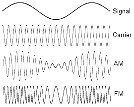
These refer to the method used to encode the pulse stream into a radio frequency that can be transmitted over the air. To explain these, you first have to understand a few terms; frequency, amplitude, pulse stream, and carrier: "Frequency" refers to how often the signal changes. "Amplitude" refers to the voltage swing (the maximum and minimum) of the signal. "Pulse stream" refers to the series of 1ms-2ms pulses that servos use, explained earlier. And "carrier" refers to the very high frequency that is used in the actual radio transmitting, and is much higher than the pulse stream that servos use.
|
|
|
This picture helps to illustrate the idea of AM and FM modulation. The data signal should actually be a square wave since R/C radios use square-wave pulses, but the resulting AM and FM signal is easier to see when a sine wave is used for demonstration. Signal: The first waveform would be the data signal to be modulated (again, it would actually be square wave pulses). Carrier: The second waveform is the high frequency carrier signal. AM: The third waveform is the data signal amplitude modulated onto the carrier signal. Notice how the amplitude of the carrier changes in proportion to the data signal. FM: The last waveform is the data signal frequency modulated onto the carrier signal. Notice how the frequency of the carrier shifts in proportion to the data signal. |